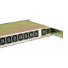
CANFORD MDU5 AC MAINS POWER DISTRIBUTION UNIT – 12x IEC outlet – IEC inlet with IEC loop-out
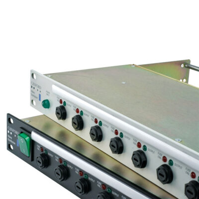
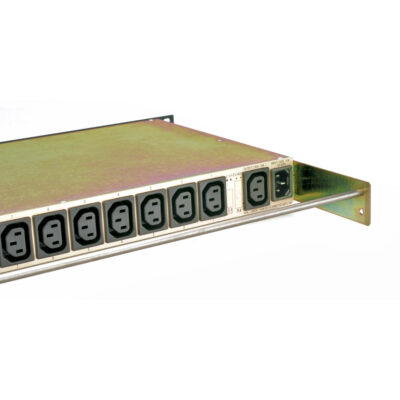
This range of twelve-way, IEC outlet, AC mains power distribution panels with a 10 amp IEC inlet and IEC ‘loop-out’ outlet, is housed in a compact 1U rackmount case. The loop-out feature provides an un-switched, direct loop-through power outlet to supply equipment that must remain powered when the MDU is switched off, or to supply to a second MDU. All versions have on the front panel an illuminated power rocker switch or an un-switched neon power present indicator, fuse and dual LED indication of power status for each of the output channels. Inlet and outlets are on the rear panel. Versions with sequential switch-on, with filtered inlet, and with both sequential switch-on and filtered inlet, are available.
NOTE: Current drawn from the ‘loop-output’ must be included in the total current calculation. Care must be taken not to exceed the maximum total load of the MDU.
The fuses on the front panel have adjacent green and red LEDs. Green illuminated indicates that the circuit is powered correctly. Red illuminated (and green off) indicates that the fuse has failed.
All outputs are numbered front and rear for easy identification and a designation- strip holder with snap-on cover is fitted on the front panel. The paper strips supplied may be inserted before or after installation; 7.5mm of printable height is available. Autocad templates for printing designation strips are available for download from the Tech Zone at www.canford.co.uk or by contacting Technical Support. Spare designation-strip inserts (not suitable for printers) 45-3082 and spare clear covers 45-3092 are available.
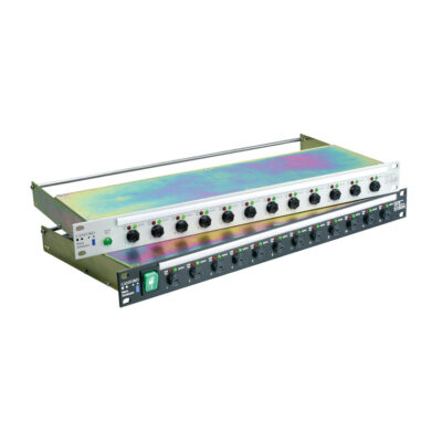
Lacing Bars
As IEC cable plugs vary enormously in size and design it is not possible to define a ‘universal’ connector wire retaining clip. To overcome the challenge of securing all IEC connector types both re-wireable and moulded, a single lacing-bar is fitted as standard. The stainless rods may be fitted in a variety of positions to take account of cable connector size. An additional rod may be ordered separately and fitted, which is particularly suitable where connectors of different heights are inserted or where excess cable must be doubled back. An example would be when ‘double ended’, fixed length, moulded AC mains cords, such as the IEC-Lock types, are used.
Standard
The front panel has an illuminated switch or un-switched neon indicator, independent outlet fuses with status indicators. The rear panel has a 10 amp IEC inlet , 10 amp IEC ‘loop-out’ outlet and twelve 10 amp IEC outlets. An earth stud is fitted.
Sequential Switch-on
These are as the standard type but, in addition, to avoid overloading the supply, the outputs are sequentially switched on when power is applied. This delay is vital where a number of pieces of equipment drawing a high ‘inrush’ current, such as CRTs, power amplifiers or equipment fitted with switch-mode power supplies, are connected to a single MDU. This sequential solution may also be used to switch on equipment in an audio installation prior to the power amplifier to avoid ‘clicks’ and possible damage to loudspeakers.
The delay between successive outputs is preset at 300mS, but an internal control allows adjustment between approximately 30mS and 660mS. Outputs are switched using relays controlled from a microprocessor. The top cover is user-removable to access the sequential switch-on delay adjustment control. In the case of switched versions, if power is connected to the unit when the switch is ‘off’, no power is supplied to the outputs. If the switch is ‘on’, the outputs will be powered up sequentially as normal.
Sequential Switch-on And Switch-off
Similar to the Sequential Switch-on types above, these also are based on the standard types, but have a control activating the ‘start’ or ‘stop’ sequence. The control is a latching rocker switch, but, it should be emphasised, does not switch the supply itself. When power is supplied to the MDU, an LED shows that power is present. If the control is in the ‘stop’ position, no power will supplied to the outputs. Changing the control to the ‘start’ position will cause the outputs to be switched on sequentially. Once the sequence is complete, changing the control to ‘stop’ will cause the outputs to be switched off sequentially in the reverse order.
If the control is changed to ‘stop’ during the ‘start’ sequence, the sequence is stopped and the outputs which are on will be turned off, sequentially, in reverse order. If the control is changed to ‘start’ during the ‘stop’ sequence, the outputs which have been turned off will be turned on again sequentially, in the usual ‘start’ order.
If power is applied to the MDU when the switch is in the ‘start’ position, say after a power cut, the outputs will be turned on, sequentially, in the usual order. If power is taken away from the MDU when outputs are turned on, either during a sequence or not, all outputs will turn off together.
The delay between each successive output when switching on is preset at 300mS, but an internal control may be accessed by removing the top cover which allows an adjustment between approximately 30mS and 600mS. The delay between each successive output when switching off is the same as set for the switch-on delay.
Filtered
These are as the standard type with a high-performance filter, fitted internally, that helps to protect sensitive electronic components connected to the MDU against mains-borne interference and to reduce the audible effects of spikes and dips in the mains supply.
Sequential Switch-on Plus Filtered
These versions combine the features of the Sequential switch-on and Filtered types.
Sequential Switch-on And Switch-off Plus Filtered
These versions combine the features of the Sequential Switch-on and Switch-off and Filtered types.
All types are available finished in Dawn Grey or Black front panels, with either red or green illuminated switch or ‘input power present’ neon indicator on the front panel.
Mating connectors are NOT included and should be ordered separately as required.
Required accessories: Input connectors: Bulgin, stock code 42-154 or Schurter, stock code 42-051. Loop-out connectors: Bulgin, stock code 42-153 or Schurter, stock code 42-054. Output connectors: Bulgin, stock code 42-153 or Schurter, stock code 42-054. Moulded mains leads: A large range are offered, see AC Mains Power Leads. Locking, moulded, mains leads: Patented, locking IEC leads, see AC Mains Power Leads – IEC-Lock. Optional accessories: Switch guard plates, see below. Additional lacing bar kit.
Technical Specification:
| Voltage: |
198-254V AC |
| Maximum outlet load: |
10A per outlet |
| Maximum total load: |
10A, including loop-out |
| Outlet fuses: |
10A (T) HBC ceramic, to BS EN 60127 |
| Maximum in-rush current: |
100A (MDU-S versions) |
Dimensions and weight:
All types are 1U, 19-inch rack mounting, 44 x 483 (h x w) mm.
Switch Guard Plates
A switch guard-plate may be fitted at the time of installation or retrospectively to Canford MDUs to avoid units being accidentally switched off (or on). The central cut-out gives finger access and a clear view of the illuminated switch. Note: Different types of MDU require switch guards of different sizes, see information in descriptions.